|
|
Post by jules on Aug 27, 2016 15:52:29 GMT
To whom it may concern, Here's another something that shows that the gunports were formed by the frames. Witsen, in both the 1671 and 1690 version of his book, shows the following drawing of the gunport construction. (Witsen, Architectura, 1690, 'page 168', 'OO', between pages 168&169)  In the description of this drawing (1690, page 174,II,13), Witsen explains that the two letters 'c', that are inscribed in the two vertical posts in his drawing, describe the 'stutten', the higher pieces of framework, placed between the 'oplangen'. 'a' and 'b' are the chocks (klossen), the upper and lower gunport sills, placed between the frameparts. Kind regards, Jules |
|
ara
Junior Member

Posts: 69 
|
Post by ara on Aug 28, 2016 14:58:46 GMT
Hi, Jules!
I think, the whole idea of Sturckenburgh is to form the ports with the frame timbers with consideration of the stuurlast-waterline as basis. But because the upper gunports are usually smaller than the main ones, doesn´t that necessitate at least some tilting of the stutten, the highest frame parts? So maybe the truth lies in the middle? No tilting of the buikstukken, sitters, oplangen, but of the stutten? Ab Hoving pointed out, that "a frame" didn´t exist in dutch shipbuilding of these times, only the inhouten, when they were ready to be put in. The stutten are the latest parts of the framework and the most vulnerable; they were often repaired or exchanged anyway. But they do form the upper gun ports according to Witsen and Sturckenburgh. So this is my suggestion: Let´s not talk of tilting or non-tilting of the "frames", but only tilting of the stutten. Bye, ara
PS. I´m glad to read, that Mrs. Baldewijns is still in charge. She and Fred are colleagues, after all. |
|
|
|
Post by jules on Aug 29, 2016 10:10:59 GMT
Hello Rein, When you, after all that's been said the last weeks, still believe that Dutch ships in the 1660s and 1670s were built with tilted frames, be my guest. But, if I may ask, where is the proof? We've covered the following 'proof' for the tilting: 1. Photographs of the Hohenzollern model; mainly the nail patterns. Photographs can not be trusted and the construction method of the model is not clear. 2. Plans of the Hohenzollern model. There are different verslons of the plans. The most trustworthy show parallel gunports. 3. Vasa has tilted frames. So what? 4. Sturckenburgh drawing shows tilted frames. Au contraire: it shows parallel frames. 5. Archaeological evidence. The bits we have, show parallel frames. 6. Deck beams have to fit between the frames, like in Vasa. This is not so. Now you come up with 'new proof': 1. The different sizes of the gunports on the different decks dictate tilted 'stutten'. 2. Hoving says frames do not exist. 3. 'Stutten' were placed last and were often repaired so were tilted. And here are my answers to the new proof: 1. The 'problem' of the different sizes of the the gunports can be solved without tilting the 'stutten'. Many have done so in the past, and even I managed to do this. So you can do it to. Clue: timber and room are not the same size. 2. What Hoving tried to emphasize with this remark, is that the frameparts were not connected to eachother. He did not mean to say that there were no actual frame parts. Witsen, Van Yk and Hoving are very clear: a frame consists of 7 parts: 1 buikstuk, 2 zitters, 2 oplangen, 2 stutten. 3.  No matter how you look at it, Sturckenburgh doesn't show tilted frames nor tilted 'stutten'; all frame parts are parallel. New proof would be: I visited the national archives and found a 17th century technical drawing showing that the frames were tilted. (Werner and I covered thousands of files the last 20 years or so, but haven't found it. But maybe you have.) Let me add some new 'proof' you (and Peter) published on the German forum: 1. A photograph of the inside of the Hohenzollern model shows the frames, and thus the way the model was built. 2. The Gent model has frames, at least Birnie seems to indicate so, so the Hohenzollern model has frames. 3. About the way the Hohenzollern model was built: 'Es gab für Sie keine alternative Bauweise' (they wouldn't know how to build it differently than plank on frames). Here we go: 1. Really, this is the proof for how the model is built? You have to come up with something better than that. 2. Even if the Gent model has frames, that does not mean the Hohenzollern model had. 3. There were a lot of different methods for building models in the 17th century. I already mentioned the Prins Willem with its solid hull. And, after reading the German forum, I feel like I have to add: the Hohenzollern model is not holy. As Jan (Amateur) already said: don't focus to much on the model, and like Fred already said: even if the Hohenzollern model shows tilted frames, that does not mean that the actual ships were built with tilted frames. You two guys, Peter and you, seem like you are part of the Hohenzollern-cult: no one can say anything about this model or you guys have to ok it. What made you two into the highpriests of this cult? Please add something meaningful to the discussion, and do not try to push people in drawing the wrong conclusions. Come up with arguments, not pressure. You may think, believe and say whatever you want, but that, in itself, doesn't make it true. Rein, in this forum you already mentioned your doubts about the hull shape of the Hohenzollern model. Has that critical look disappeared completely? You can stare at those photo's forever, they will not tell you everything. There are other sources to study. And what do we have to think of a remark on the German forum like: a model of a Dutch ship showing the frames, can only be built by someone who is a genius, or someone who is a lunatic ('verrückt)? There are some Dutch model builders who built models with frames, I only name Dik, Blom and Hoving. I do not consider these people to be lunatics. These people used the building of their models to check if their theories about Dutch shipbuilding were sound. They didn't mind starting all over again if something was wrong; and so they learned. And what they learned, they published in books, so that we can learn from their mistakes. Read those books, and learn. Do not say they're just a bunch of lunatics, because they came to a different conclusion than you. And Peter has a big advantage over the guys I mentioned, he actually knows where the frames are in the Hohenzollern model, he does not have to guess or work it out, he knows. So why not build them? Come to think of it, could you ask Peter if he can make a plan of the frameparts he found in the Hohenzollern model? I won't get into Peter's thoughts about who and how many built the Hohenzollern model. You might as well say the model was built by 16 virgins. Again, what you think is right, not necessarily is right. An argument would be: I checked the pay roll of the Admiralty of Amsterdam of 1666, and found an entry for the payment of six model builders during six months. There's no escape: do research, don't make it up. (I did, didn't find it though.) Let's get back on topic. Please show me the proof for the building of ships with tilted frames. Peter, in his first post, said: 'Some scholars found my observations 'interesting' others reacted downright furiously.' What arguments did these scholars use? Please let me know, so we can help this discussion forward. If Peter means me with one of the scholars he was in contact with, the arguments I used to dismiss his theory the last couple of weeks, are the same arguments I used a year ago to dismiss his theory. Hasn't anything new come to light since then? Or please answer this question first: why would they bother to make tilted frames? A whole lot of work, for what? You have this parallel pre cut wood, and now you have to work all these parallel planes to make the frames tilt. Why? What is the purpose of this action?
Kind regards,
Jules
ps Yeah, great news about the Vasa-Gent contact. Let's see if this gets the model out of the box permanently.
|
|
ara
Junior Member
Posts: 69
|
Post by ara on Aug 29, 2016 11:34:30 GMT
Hi, Jules. Well, I have only tried a middling position between the two of you, Peter and yourself. But I do not want to be dragged into an endless quarrel. I don´t know anything about that thing that is apparently going on between the two of you. So I will read all the arguments pro and con again with curiosity and also with pleasure (it´s extremely interesting, after all). No doubt your arguments are very profound and learned. But for now I will keep my personal conclusions about framing to myself. For I consider myself pretty neutral in this, I´m not the highpriest of anything. Don´t forget, I´m not a scientist, I´m just a shiplover and enthusiast. My possibilities for doing research are limited, basically to the Internet. I feel strongly, that I´ll have to wait for the outcome of the Gent model research of Fred and yourself. That´s an exciting thing in itself over the coming months (maybe years?). Good luck with that! Bye Rein.
|
|
|
|
Post by Peter Jenssen on Aug 30, 2016 5:36:13 GMT
Or please answer this question first: why would they bother to make tilted frames? A whole lot of work, for what? You have this parallel pre cut wood, and now you have to work all these parallel planes to make the frames tilt. Why? What is the purpose of this action?
Hi Jules, Many good points well made. Still, the last question has me interested yet again. Couldn't agree more, why do extra work indeed? But which one is it that means extra work? Are machine sawn timber and Vasa's tilted frames mutually exclusive? (Hybertsson and de Groote had access to -indeed control over- such a mill when they built the Vasa, as was previously discussed) 3rd post in this thread, by Fred, states that: The reference surface for the tilted frames in the Vasa, is the bottom planking. Parallel, pre cut wood laid on curved bottom planking would therefore lean, unless you do the extra work needed to make them stand vertical. The bottom of the Vasa is approximately curved as per the red line in the attachment from the TotalStation data plot Fred attached (18 Aug), -the tilt of the frames can be seen to be consistent with square timber placed on the bottom. Isn't tilted frames seen in Vasa then what you would get with straight cut timber (such as machine sawn timber)? (If this extra work was actually avoided, any presence of tilt or not should be possible to deduce from the curvature of the bottom? At least for shell first construction?) Peter (J) |
|
|
|
Post by fredhocker on Aug 30, 2016 11:30:32 GMT
One issue which has not been discussed yet, which may be helpful, is that the apparent change from tilted to parallel frames around the middle of the 17th century coincides, more or less, with the abandonment of the bottom-based assembly sequence. I do not think that is a coincidence. If the frames are the first element erected on the backbone, instead of the bottom planking, there is no reference surface to which to orient the frames, and thus no practical advantage in tilting them. If one instead is deriving the frame shapes from a drawing or geometrical rule (rather than from the bottom planking), so that they can be set up before the planking, then it is more or less essential for them to be parallel for the geometry to work and the hull to be fair without wasting a lot of timber.
To me, this is the more convincing argument for why this change occurs, not the introduction of machine sawing. Even with hand saws, one normally saws the two sides of a frame timber more or less parallel. In either case, tilted or parallel frames, there will be some work involved in bevelling the frame faces to make them fair and plankable, so there is no work "saved". Ready-sawn frame timbers are only sided, the interior and exterior faces have to be cut at a changing angle to match the run of the planking and ceiling, which is not possible with 17th-century sawmill technology. One could just as easily use mill sawn frames in tilted or parallel construction, since all that the sawmill is accomplishing is making frame blanks of even thickness efficiently. Roman ships had evenly sided frames (with handsaws), as did Viking ships (with axes) - the sawmill is simply a more efficient tool for converting logs to rough shapes. We are confusing two different parts of the conversion process here, siding (cutting the frame to width) and moulding (cutting the frame to the correct cross-sectional shape). Tilted frames can be set up roughly square to the plank surface, so the exterior face of the floor timber can be square to the sides, a cut which could be made on a sawmill, but from the turn of the bilge upward, the face will still have to be bevelled by hand. Frames set parallel to each other require changing bevels on the face against the planking, a cut which cannot be made on an up-down saw of 17th-century type, and so the moulded faces of a mill-sawn frame will need to be cut with a hand saw, ax or adze. One could argue that certain parts of the frame shaping process are more work-intensive with parallel frames than tilted frames (which helps to explain why builders used tilted frames in the first place).
It is thus not a matter of efficiency in conversion that drove this change, but a big-picture change in the fundamental concept of how the hull shape is determined, reflected in the assembly sequence and the orientation of the frames. Sawmills and gunports are side issues here - we have started to lose sight of the forest in a focus on trees.
Fred
|
|
|
|
Post by jules on Aug 30, 2016 11:37:02 GMT
Hello Peter (Jenssen), Thanks for sharing your train of thought. Let's take it back a step. We should not forget that one of the main insights that has emerged from this discussion, is that there is a significant break in building style between the building of Vasa, and, approximately, 1652. Reread Fred's post of August 18; I quote: 'One thing that does seem to be emerging from this discussion, which I don't think I heard before in the academic side, is the apparent change in framing practice around mid-century.' So, I think, it is justified to say that Vasa does not represent the 1660s and 1670s Dutch shipbuilding style. I know that this is hard for you Vasa die hards to accept, but Vasa is not the only thing we have to prove how Dutch shipbuilding works. Especially when we have to concentrate on the 1660s and 70s. We also have to remember, we have some good evidence of how it was done in the 1660s and 70s. We have some excellent books from that era, and, I have to repelt it again, we have the very important Sturckenburgh frame drawing, which shows something else than Vasa shows. In this drawing we see parallel frames which are perpendicular to the waterline. And, since this complies with what we know from other sources, we must come to live with it, this drawing actually proves something. (But, read what Fred said about this drawing on Aug.22.) What I'm trying to get across, is that Vasa is not Dutch shipbuilding in the 1660s and 70s. In my view, it is a whole lot more work tapering all the frameparts, than make an adjustment to make a framepart stand tilted on the keel. What you have to do to make a ship with tilted frames, is make all the frameparts taper. It's not easy to make tapered wood in a sawmill. And we know that's not what they did, they made parallel wood in the sawmills: the wood was sawn with two adjacent sawblades at the same time, set at the required distance, resulting in parallel wood. (I don't know how the wood was sawn at the Vasa site. And I don't know which wood was sawn on the site: only the planks, the frames also? Fred will have to answer this one.) To make tapered wood you would have to work all four sides of a piece of timber. In the case of using precut wood, you only have to work two sides of the piece of timber: the outer- and inner side, but not the sides that were preworked by the sawmill. Willem Vos recently wrote a book about what he has learned when building the Zeven Provinciën replica in the 'old style', 'vlak eerst', bottom first method. He describes exactly how the precut wood was fitted into the shell of the hull. There were no problems, finding the method of measuring the wood was all he had to do. For the rest the frames were simply placed against eachother, with their precut sides, guaranteeing a tight fit. This is also what we see in the E81 wreck. Here's a picture of the wreck in situ. (Picture RCE). 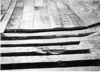 Don't forget, no space between the frame parts,everything has to be tightly packed in the bilge. What we can not see here, but what we know from the contracts and the Sturckenburgh drawing, this tight packing was also required, higher up, at the lower wales. I think this tight parking is easier to achieve with straight frames, than with tapered frames. The overlap of the frameparts was considerable: about two meters in a large ship. And, the E81 wreck shows that the frames are parallel, not tilted. For another example of this placing of frames against eachother, we can look at how the Navy Board ship models of the 17th century were made. Here's a picture. (NMM-Greenwich)  If I would have to choose between making a ship (or a model) with parallel frames, or a ship with tapered frames, I know what I would choose. I think that is also the reason why everybody shies away from making a framed model of Vasa, not easy making everything fit without the help of some parallel frames. Kind regards, Jules PS Darn, the picture of the model shows tilted gunports. Sorry. |
|
|
|
Post by Peter Jenssen on Aug 31, 2016 6:36:10 GMT
Hi Jules,
Not forgetting at all that Dutch shipbuilding changed style mid 1600's. Seems very clear.
(Which it also did in Sweden, but for different reasons, -the transition to English style.)
I'm merely trying to picture what needs to be done to shape the timbers suitable for a bottom first design.
So, if the main concern is not the bevel, but the tapering, that's a different aspect.
What I was trying to visualise was what happens if you put squarely (non bevelled) sawn timbers on a floor that curves upward.
Seems to me that if you do not bevelling the bottom surface, they will start leaning as you go aft.
(Of course you can make them stand straight, if you do the bevelling)
I'd like to speculate on the following of your questions above, even though you are asking Fred, if you don't mind?: :-)
"I don't know how the wood was sawn at the Vasa site. And I don't know which wood was sawn on the site: only the planks, the frames also? Fred will have to answer this one."
Perhaps planks and straight timber would be cut closer to the forest where they are harvested, due to them being easier to ship than logs would be?
Hydro powered "Crown sawmills" would have existed since at least 100 years earlier.
(I believe Gustav Vasa took control over some in the beginning of the 1500s?)
Perhaps, planks, beams and any straight timber shipped in, frames cut on site?
Thank you for the interesting picture of the E81 wreck.
This part looks very flat, and as you say, very tightly packed towards the turn of the bilge.
The overlapping, 'packed' timbers correspond really well with the model picture.
For the floor timbers, are their width equal to the spaces between them?
Tapered frames is not so hard and is done by model builders.
Many model builders build late English 18th century fully framed models with parallel tapered frames.
The floor timber, the futtocks and the top timbers are all cut from different thickness stock.
This results in a taper. (if you are following the practicum by David Antscherl)
They are installed vertically though.
For me, building a hull with tilted timbers would pose the biggest challenge during the process of lofting.
Then, after that, the difficulty in assembling timbers that are not actually attached to each other.
Cheers!
Peter (J)
|
|
|
|
Post by jules on Aug 31, 2016 9:55:44 GMT
Hello Fred,
Our posts crossed eachother yesterday. So if I double up in answers, that's why. Anyway, thanks for your reflections.
I don't think it's that easy to link the change from tilted to parallel frames to the abandonment of the bottom-based assembly sequence. After all the E81 wreck shows that the new type of framing, that with the parallel frames, existed in combination with building in the bottom based sequence: E81 is built bottom first, and shows parallel framing.
And then there is still that other nagging bit: the Dutch used drawings and specifications for building their ships early in the 17th century, and still prefered to use the bottom based method untill at least far in the 1660s, and probably untill much later. So the combination of bottom based and parallel framed lasted for quite some time. It looks to me that the building with the bottom based method lasted longer than the building with tilted frames. At first sight, I do not see a linked timepath between the two. It looks to me that bottom based shipbuilding outlasted tilted frame shipbuilding. But this is the quick reply; would like to hear more from you about this.
Back to the sawmill.
Before the invention of the sawmill, there was no difference in producing parallel wood or tapered wood. The handsawers had to saw each cut from a tree, and that lasted days. No matter if the second cut had to be parallel or not, that lasted days as well.
After the invention of the sawmill, the cuts were made simultaneously and parallel. All of a sudden the process had changed. It went from: doesn't matter if the frames are tapered or not, to: it is taking a lot more trouble to make tapered frames. All of a sudden there was a difference in producing parallel wood or tapered wood.
And when you have parallel wood, why not make parallel frames from it? Nothing stops you from doing so.
For me, the choice between using parallel wood or tapered wood, would be the choice between being in competition or not.
Let's compare. With tilted frames siding and moulding have to be done by hand. With parallel frames siding has been done by the sawmill, the moulding has to be done by hand.
So the saving is in the siding. That work has been done by the sawmills: faster, cheaper and of consistent quality. It was a no brainer for the shipwrights: they jumped on it straight away. The only problem was in the supply chain: how do we get enough of this pre cut wood on the wharves?
And to link this back to the topic again; in the 1660s and 70s a lot of this pre cut parallel wood was available. What would have made them build ships with tilted frames then?
Peter (Tromp) claimed it had to be done because of the building process: the deckbeams have to tilt because the decks tilt, and the deckbeams have to be placed between the frames, so the frames have to tilt. This turned out not to be so, but at least it's a reasonable train of thought.
The other reason would be that the shipbuilder had to do more work in bevelling. But in my view this extra work is easily compensated by the saving of work for tapering the frames. And E81 shows the shipwrights built this way: bottom based, parallel frames.
My problem is that I can not think of a single reason why the frames had to be tilted. And when it is easier and cheaper to build parallel frames, why would the shipbuilder choose to build tilted frames then?
Kind regards,
Jules
|
|
|
|
Post by jules on Aug 31, 2016 11:32:18 GMT
Hello Peter (Jenssen), Thanks for the answers. I hope the post to Fred helped you in some way. To answer your 'perhaps planks, beams and straight timber shipped in, frames cut on site?', Fred has to check on the ship if he can find out which parts were hand cut and which parts machine cut. I hope for him someone else has already done that for him. The sides of the frames of E81 look machine cut to me; very smooth and straight. But I'm no expert. If the floortimber width equals the spacing in E81, look for yourself. Here's a section of the wreck.  Your remarks 'tapered frames is not so hard and is done by model builders', and 'parallel tapered frames', got me confused a bit. But I think you mean these kind of frames.  I wouldn't call these tapered frames though. The frames still consist of parallel sawed frameparts, but have different widths. For me tapering is a gradual diminishing in size, not a diminishing in steps. So I wouldn't call these frames tapered frames. But hey, what's in a name. I prepared this stupid little sketch to show what I mean with tapering frames. Left: parallel and perpendicular; right: tapered and tilted.  And this is the precut wood for the parallel frames, be it of smaller ships.   Hope this helped. Kind regards, Jules |
|
|
|
Post by tromp on Aug 31, 2016 16:02:47 GMT
I've done an experiment. I placed a long strip of sticky tape to the side of the keel as upright as I possibly could get it by eyesight. I then graduatly moved upwards with the tape gently pressing it against the hull but letting the tape find ist own way instead of me sticking it where I wanted it to go.
Here's the result:
 bilder hochladen kostenlos bilder hochladen kostenlos
There is a slight tilt in the angle above the main deck. I know that the "Inhouden" consisted of several pieces instead of one strip but this irrelevant for the time being. For me this is exactly what frame-pieces would behave like if they had perfectly square sections, instead of rhomboidal sections. There is no need to bevel the pieces, the left cut edge of each facia can be a perfect mirror-image to its right cut edge. There is no need for any tricky fitting process bevelling the frames to follow the lines of the Planks. For me this would represent a significant advantage in the building process.
This means that in a horizontal longitunal sections the Frames would look like as in A:  bild hochladen bild hochladen
and not as in B.
I am not saying that this is the ultimate explanation. It's an idea of mine, that to me makes sense but perhaps only with the shell-first method.
If it ever came across that the tilted frame method was the one and only method for me it wasn't meant that way. For me the tilted frames only really makes sense with the shell first method. But as Fred said earlier, this method wasn't ended at the flick of a switch. It gradually phased out in the second half of the 17.th century. I believe that in Vasa's time the Shell-first method with tilting frames must have been very wide-spread perhaps in those days it was the most commonplace method. But after 1650 it was replaced more and more by upright-frame-first method, the HZM by chance being one of the last ships (models) to be built that way.
Regards Peter
|
|
|
|
Post by Peter Jenssen on Sept 1, 2016 7:23:15 GMT
Hi Jules, Thanks for the information and interesting pictures. I can't really tell from the pictures the relation between floor timber width and their spacing... I do mean that I have seen model builders doing a smooth taper for their frames. No steps. Actually sanding the 'steps' off after assembling the frame. It may very well be that they are historically incorrect in doing so, but it did not seem very hard to do. (Looking at some examples of plans on the web, I can definitely see several examples of English 'Disposition of Frames' plans with the arrangement you show above though, no tapering on the individual timbers) They had a mill for the shipyard in Stockholm as well, so both on site and off site could be machine cut in that case. For the sketch, I can see how that could be a serious problem of increased work, having to taper the frames like that. Tilted frames, sketched in similar style?: (not so large gaps of course)  Cheers, Peter |
|
ara
Junior Member
Posts: 69
|
Post by ara on Sept 1, 2016 12:21:59 GMT
Hi Jules,
Maybe you also have a photo of the bow frames seen from inside of the E81 model for us? I think the first ones are perpendicular to the inner curve of the stem post. How are they reproduced on the model? I surely would like to know. Thank you! rein
|
|
|
|
Post by jules on Sept 1, 2016 16:03:29 GMT
Hello Peter (Jenssen),
Thanks for the replies.
About the relation between the floor timbers width and their spacing in the E81 wreck. Yeah, that's the problem with these wrecks, they dry, and the geometry of the parts changes. I took the measurements a while ago anyway, but I don't think they're very reliable.
But we have written sources for the timber and room values. There are contracts that mention them, and Witsen and Van Yk give some general rules. In general the timber and room do not have the same value. The timber (the width of the floor timber) is usually wider than the room (the distance between the floor timbers). Since the 'zitters' are placed between the floor timbers, this means that the zitters are not as wide as the floortimbers. When building with parallel frames, the floor timbers and the second futtocks (oplangen) have the same width, and the first futtocks (zitters) and the third futtocks (stutten) have the same width, but the width of the floor timbers and second futtocks is larger than the width of the first- and third futtocks.
Then to your sketch. Your remark 'not so large gaps of course' says it all. Like stated before: no gaps allowed at the overlapping of the frame parts. And when you place a tilted parallel framepart against another tilted parallel framepart with a different tilt, this results in a tapering gap. So you would have to work the frameparts to make them fit properly against each other. And over a long distance: as mentioned before, the overlap can reach a length of 2 meters. In my view, a lot of work.
Kind regards,
Jules
|
|
|
|
Post by jules on Sept 3, 2016 12:40:37 GMT
Hello Peter (Tromp),
Thanks for sharing the result of your very interesting experiment. But why did you use tape? Probably because it 'flows' easily against the hull, but wood doesn't. I would like to suggest that you do the experiment again with a strip of wood. The strip should have parallel sides, like the tape, and a width of approximately one foot (to scale of course). Also the strip has to be tapered from bottom to top: 1 foot, 11 inches, for the bottom, and half of that for the top: 5,5 inches. All this to get a closer representation of the real frames. And it would be nice if you could make two, three or more of these strips, so you can place them against eachother. Let's see what happens.
Thank you for the sketches; very clear. But, as mentioned before, the 'inhouten' (frame parts) have to be placed against eachother in the bilge and at the lower wales: the contracts for these ships are clear: no spacing allowed. I think that when you place the frames with their perfect square sections against eachother, that will result in a wedgeshaped opening between the frames. To avoid this, the sides of the frames would have to be worked to make them sit flush against their neighbouring frames.
Then, if you let me, to your 'the tilted frames really only make sense with the shell first method'. Like said before, E81 was built shell first, and shows parallel framing, not tilted framing. So we can maybe say that tilted framing only makes sense with the shell first method, but we can not say that the shell first method dictates tilted framing, or excludes parallel framing; E81 shows this.
(Your remark 'There is no need for any tricky fitting process bevelling the frames to follow the lines of the planks', makes me think that you think that in the bottom first building method all frames were placed against the planking. This is not so: only the lower part of the hull, up to the highest plank of the bilge, was built that way. The rest of the hull was built frame first: the planking was placed against the frames, not the other way round. For the upper part of the hull, there was no way to simply place the upper frames with their perfectly square sections against the planking, the planking wasn't there yet. But, please forgive me if I got the interpretation of your sentence wrong.)
Looking forward to the results of your experiment. Maybe we can establish in this way if your conclusion 'the HZM by chance being one of the last ships (models) to be built that way', is justified.
Regards,
Jules
|
|


