|
|
Post by philemon1948 on Feb 19, 2021 17:16:18 GMT
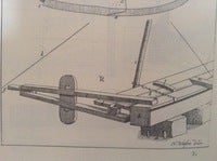
Hello Jules, I am sorry, I think I didn’t express myself clearly enough. First of all I didn’t say you are biased. I said I was, several times. And this resulted in a flawed concept and misunderstanding on my part. This is a danger that should not be underestimated. I worked for years as a ship- and millwright. Right now, the company I worked for facilitate me in making 1:10 models of some structures of this 155 feet ship I try to reconstruct. In all the years I worked as a ship- and millwright I learned one very important thing: never ever generalise. The production of traditional ships and windmills is so rich in diversity, shapes, sizes and methods that it is virtually impossible to say something about the building of these structures with certainty unless there are specific written sources. And even then, also written sources have to be interpreted. That is what I am trying to do now with van Yk’s book. I can tell you first hand how difficult it is to draw conclusions about traces in a building concerning its construction and history. Over the years I encountered many people who thought they knew, beyond the shadow of a doubt, that certain things were true. I will give two examples. Recently someone, I can’t remember his name, had the bright idea to investigate the Sound Toll Registers with regard to the question if the Dutch flutes had this strange narrow shape at the upper deck to avoid these toll or at least try to reduce it. The conclusion was this relation is a myth. But I encountered some people who were sure of this relationship. Without even bothering to look into the matter. Van Yk makes a remark about this. He says: “In ‘t kort geseid, ‘k heb nog noit eenige gegronde Reden gehoord, waarom datmen liever een Fluit, dan een Spiegel-Schip behoord te maaken”. “In short, I never heard a sound reason why one should rather build a flute than a square sterned ship”. And I think he was right. The other example I heard yesterday, which was a real surprise. For years I heard the story that the Amsterdam sawyers guild stopped the building of sawmills in the city. Because these mills destroyed their trade. This is also a myth. What strikes me in this is that discussions about these subjects are easily held hostage by these views. Unless there is someone who simply asks the question: how do you know? As I have learned from Socrates, asking questions like these doesn’t make you popular. But since that is not my intention I continue my investigations. The essential thing in what I am trying to tell you is I think your reasoning is flawed. I am not interested in being right. I am only interested in trying to get closer to the truth. You ask me to give an example of a wreck with a chine. As this wreck has not been found up until now, you regard this as proof the chine is a misconception. But you can’t say that. This is reasoning in the category: all swans are white. Until you find a black one. The fact a big ship with a chine hasn’t been found does not mean they didn’t exist. Traditional ships with a chine did exist and still do. They make a ship quite stable, much more so than a ship with a rounded and smooth bottom and bilge. But apart from this discussion, I promised to present a construction of the main frame as Witsen describes in his book. And so I will. And this construction will yield a profile with a chine. A very subtle one but still: a chine. I want to say wo last things. First about the sentence you wrote: ‘Again, Witsen does not talk much about design. He mainly talks about a building method, and gives a lot of formulas for the design of ship parts, not the actual design of the ship’. What would you call the drawing of the main frame between page 150 and 151? A building method or a design method? And could it be these two understandings are thoroughly intertwined in the seventeenth century? The last thing I would like to show is something that bothered me for years. What the books of Cornelis van Yk and Nicolaes Witsen have in common is both authors have a habit using understandings in an inconspicuous and almost invisible manner, while these understandings can have a profound impact on what they are saying in their books about shipbuilding in the Dutch 17th century Republic and our understanding of this process. One sentence van Yk wrote struck me when I first read it: “Hoe datmen, door de Slaglijn, alle Hout na Schips beloop, hol, en rond moet strooken”, “How one fairs, by the chalk line, all wood to the sheer of the ship, hollow and round”. I worked for many years as a ship- and millwright and often used the chalk line to make straight lines by lifting the strung line, saturated with coloured chalk and let it bounce back leaving a straight line of coloured chalk on the piece of wood. But how do you fair a ships hull using this line? All discussions with colleagues were fruitless. We couldn’t figure it out. Until I came across a passage in the book ‘The Evolution of the Wooden Ship’ from Basil Greenhill and Sam Manning. This passage was accompanied by a drawing which leaves almost nothing to the imagination. (Attachment) The description by Greenhill is as follows: “Here’s the look of trimming double-sawn frames to final fairness of bevel on a vessel being planked simultaneously inside and out. A tightly-pulled string guides the dubbing through the square body of the hull. The foreman works ahead of the dubbers, lining-off the lay of plank and cutting channels or ‘spots’ across the faces of various frames in order to make the tightened string lie fair along the hull. His tool is a hollow or ‘lining’ adze. The dubbers remove the wood between the spots with a straight-bladed (English) or lipped (American) adze. Dubbing is awkward, exhausting, highly skilled work. Frame bevels accurately applied to the frame futtocks at the saw pit save a great deal of labour in dubbing when plank is hung later on”. Knowing how the procedure of fairing with a chalk line works made me realise a few things. First, the design of the hull, as van Yk describes this, is done in two stages, a ‘rough’ first stage and a second stage where the definitive hull shape is established together with the exact location of the planking. This procedure of ‘dubbing off’ was still in use in the beginning of the 20th century and apparently they did this the same way in the Dutch Republic in the 17th century. Second, the knowledge about one, single, procedure can dramatically change your understanding of the complete design process of the hull or whatever process or sequence during construction. Remarkable is the fact van Yk mentions this only once and in a kind of casual manner, but for us this remark is crucial. Third, it is nearly impossible to recall an ancient building process if there is no account of some sort of this process. If I hadn’t seen the picture and the description of the process ‘dubbing off’, chances are I still wouldn’t have known what van YK meant by this sentence. Apart from that, if van Yk hadn’t mentioned this in his text, we wouldn’t have known about it at all with a subsequent flawed understanding of the process of shaping the hull which makes you think twice of making firm statements about the process of shipbuilding. Fourth, the building process is often described as a sequence. For instance: first you make the bottom, then you make the frames. But if you take the central procedure used in almost all of these building processes as a reference a complete other picture emerges. This central procedure is fairing. Fairing can be done in many different ways, with the building material itself or with tools like battens or even with a chalk line. Cornelis van Yk mentions two different approaches who are usually referred to as ‘frame first’ or ‘shell/bottom first’. Van Yk says: “Dog in Hollands Noorder-kwartier, alwaar men nog gewoon is ‘t Schips onderste Fatsoen, niet door Centen, gelijk aan de Maaskant, maar door de Planken selve, die om ‘t Schip vaaren sullen, te geven, en by haar Boejen genaamd werd (…..)” “But in ‘Hollands Noorder-kwartier’ where one is used to establish the lower shape of the ship not by battens, like at the river Maas, but by the planking itself who are fitted around the ship, a proces they call ‘Boejen' (…..)”. This sentence is an introduction van Yk uses to mention something else, the construction of the bilge, which does come out different if you apply the one or the other method. I interpret this sentence in such a way that van Yk does not regard these two methods to be essentially different which they, from the perspective of the understanding of fairing, aren’t. Establishing the shape of the bottom by battens or by the planking itself makes in essence no difference. He merely emphasises the consequence of the method described by Nicolaes Witsen which is the different shape of the bilge, something he doesn’t approve. To be continued. Attachments:
|
|
|
|
Post by jules on Feb 27, 2021 12:13:43 GMT
Hello Philemon (hallo Jaap), Thanks for explaining that you do not think I am biased. But what comes up next is your remark: 'I think your reasoning is flawed', which you explain by saying that I am trying to prove that all swans are white, while we know that black swans exist. Let me respond by saying that I am not trying to prove that all ships are round. What I am trying to prove is that ships that are built by using Witsen's bottom based buiulding method do no necessarily have to have a chine. And, please allow me, I think I have proved that. If you do not think so, please let me know. And there is a reason for why I want to prove this simple fact. There seems to be a dogma in the perception of the building method Witsen describes. This dogma dictates that all ships built according to Witsen's method show a chine. Since this dogma has a large groop of followers who do not reason by arguments, but by dictate, I wanted to make sure that you are not one of those followers of the dogma, and made the dashing statements I made. It was a sort of preselection to determine who I was dealing with, before engaging to the fullest. Because, I really do not want to start another discussion with another one of those zelotes. In your last contribution you seem to be using one of the 'proofs' for the dogma as well: a quote from Van Yk that describes shipbuilding in the 'Noorderkwartier', the North of Holland. But, like many before you, you leave out the key sentence. Van Yk's complete sentence goes like this (page 70): "..., heb ik gesien dat by sommige Meesters nog Scheepen werden gebouwd, die, in 't op, of omgaan van de Kimmen, een Plank hebben, die al dapper over d'andere Planken inkomt, en aldaar een Kimmende Naad geevd. Sulks dat het Vlak, hier door vande Kimmen, schijnd onderscheiden te sijn." Translated: "..., I have seen that some Masters still built ships, which, in shaping the bilge, have a plank that goes over the others, and gives an open seam. So that it seems that the bottom is separated from the bilge." The key phrase in Van Yk's description of course is ' sommige Meesters', ' some Masters'. Van Yk has seen this phenomenon with some masters, not with all masters. So, to me, this description of Van Yk can surely not be used to say that all ships built according to the building method of the North of Holland, Witsen's method, show a bottom that seems to be separated from the bilge. So your conclusion: "Van Yk merely emphasises the consequence of the method described by Nicolaes Witsen which is the different shape of the bilge", is not justified because it generalises about all of the ships built according to Witsen's method, while Van Yk is only talking about some of the ships built according to Witsen's method. And that Van Yk is wise in limiting his statement is clear from the fact that we have found wrecks of ships that were built according to Witsen's method and did not have the chine, or the 'different shape of the bilge' as you prefer to call it. I hope we can agree on that. Please give me your view. About the design Witsen describes with support of his drawing between the pages 150 and 151. I think we can only qualify the figure W as a design figure. Here's why. Figure W is in chapter 11 of Witsen's book. In this chapter, titled 'How one assembles the ship's parts', Witsen is describing the building process of the North. While he is in full flow describing how the round transition between the bottom and the bilge is made by using figure V, he suddenly takes a step back because he realises he has forgotten to explain how this transition was designed. This is when he introduces a discription of the design process, starting at page 151, I. And he uses figure W to explain this design process. This is how he says it himself: "The figure at the letter W, which is at the top, shows how one makes the design on paper, before one starts building the ship, ...". Witsen's text about the design is very short, and he only uses figure W as an illustration of what he is trying to explain about design. The rest of the figures on the same page, V, X and Z, are only used as illustrations of the building process, as he says so himself. To stress my point in a more general way, I am trying to fight the idea that the building method decided the shape of the hull. The design determined the shape of the hull, not the building method. Designs could be transformed into ships no matter what building method was used. Both Van Yk's southern method or Witsen's northern method could be used to make ships with round bilges or ships with angular bilges. The idea that Witsen's northern method can only produce angular bilges, can, and has to be discarded. Proving this has nothing to do with proving that there are only white swans. Thanks for describing your discovery about the fairing process here. I did read your contributions on Academia about this subject a while ago. Thanks for bringing it over here as well. It would be nice to see your reconstructions and models of the 155-footer here. Also looking forward to see your reconstruction of Witsen's main frame, with a 'very subtle chine'.  To be continued. Jules |
|
|
|
Post by philemon1948 on Mar 2, 2021 17:54:36 GMT
Hello Jules, Nice to see your reaction. Thank you for that. Before I try to answer the other issues you mention, I promised to give a reconstruction of the main frame as Witsen describes. The way I do this is similar to the way I try to get a grip on van Yk’s work. Lets first examine drawing ‘W’, part of plate 52 (1671), the first attachment. The division in units of the width ‘bc’ and the height ’ab’ is 20:8. This is exact the ratio between the width and height given for Witsen’s 100 feet pinas which is 1:0,4, 25:10 feet. This is also the ratio Grebber gives in his table. So these 20 units represent 25 feet which is a bit strange. This raises two questions. Is this a representation of the main frame of this 100 feet pinas? And is the method described to construct this main frame a universal one, so applicable to every ratio, within certain limits, of the given width and height of a ship? My answers to these questions are ‘yes’ and ‘yes’ but they are assumptions. As Witsen puts it, ‘hoe datmen de verdeeling op ’t papier maeckt, eer men de Schepen aanlegt’, (how one make the distribution on paper before one starts to build the ships) suggests a universal method. And the ratio width:height is identical to Witsen's 100 feet pinas. So I conclude: the presented method is, in particular, a reconstruction for the main frame of the 100 feet pinas and it is, in general, meant to be a universal procedure. What we see is a rectangle ‘abcd’ with baseline bc’ which coincides with the upside of the keel. What strikes me first is the fact the sequence ‘abcd’ of this rectangle is clockwise. I would start upper left with ‘a’ and end upper right with ‘d’, so you read the drawing from left to right. This is also the way Nicolaes must have drawn this picture but due to the translation in copper the whole drawing is mirrored. So the units of the height were also initially drawn at the left side which seems much more logical to me. In Europe we tend to read from left to right. The fact I think Witsen himself made the drawing for this picture is because underneath the whole plate 52 ’N. Witsen delin.’ can be read, which caption is used on every plate concerning the actual building process. If Witsen also made the copper plates himself he would have signed the plate with ’N. Witsen fec.’ or ’N Witsen inv.’. This mirrored appearance can be detected on more plates of which the gondola, attachment two, (plate 86, 1671) is the most striking example. The place where the gondolier stands on this plate is on the starboard side of the ship while in reality the gondolier stands on the port side. If you measure the width ‘bc’ and the height ‘ab’ in the actual drawing this is 97,5 x 40 millimeter, 1:0,41. So the drawing is not exactly accurate. This is also true for the straightness of the lines and their perpendicularity to each other. The frame ‘abcd’ constitutes as said, the width of the ship and the height. The width is on a 1:1 scale 25 feet, the height 10 feet. If you want to establish the scale of the picture, which line do you choose? If you choose the baseline ‘bc’ the scale is 1:72,60. If you use the height ‘ab’ the scale is 1:70,78. This baseline ‘bc’ is at the picture 97,5 millimeter wide. Since it is the longest line in the picture we will use the scale derived from this length, so 1;72,6. It doesn’t really matter since in the end you compare ratios. The keel itself is according to Witsens ratio’s high 1,25 times the thickness of the inside of the stem, which is 10 inches for the 100 feet pinas, and the width 1,5 times. So the keel is 12,5 inches high, 0,32 meter and 15 inches wide, 0,39 meter. In the drawing the width of the keel is 6,5 millimeter which is in reality 6,5 x 72,6 is 0,47 meter. So the keel is too wide. The height of the keel is 4,5 millimeter x 72,6 is 0,33 meter, which is more in line with the ratio Witsen gives. To be continued. Attachments:

|
|
|
|
Post by philemon1948 on Mar 3, 2021 13:11:14 GMT
Hello Jules, Besides the frame ‘abcd’ Witsen provides more lines and points. I think it is useful to have a look at the original text in which Witsen describes his method of construction. The text is taken from the 1690 edition and can be found on page 169. The description is for the already mentioned drawing’W’, attachment one. “De gestalte op de plaat by letter W, welke boven aan staat, vertoont hoe men de verdeeling op het papier maakt eer de Scheepen angelegt werden: a en d is het verdek, uit e en h werden de bogten getrokken, g is de snyding aan de kimmen, f en l is het hoogste van 't vlak, y de kiel, en k de plaats daar 't kolsem en de buikstukken komen over te leggen, gelyk de print alles uitwyst. Doch om zeker te gaan met het vallen van de oplangen, en buigen der kimmen, op papier, of tot model, en afbeeldtzel, te maken, zoo maakt men een linie op de holte, en verdeelt de wydte in vier deelen, zettende de voet van de passer op een derde der vier deelen, en trekkende een kring wat laeger als twee derde van de holte, als blykt by g, op de holte van de kimmen; en als 't vlak wydt is, en ryst, drie vyfde deelen, als blykt by f, zoo zet men d'eene voet van de passer op f, en schrabt een schrabbe by h, en een andere op g; daar na schrabt men weder by h, en zet de voet van de passer op dat middel-punt, trekkende de bogt van de kimmen, gelyk men ziet van g tot f gedaan te zyn. Van f tot l, en van y tot k, is het ryzen van 't vlak.” Translated: The shape on the plate at letter ‘W’, which is positioned above, shows how one makes the distribution on paper before one builds the ships: a and d is the upper deck, from e and h the curves are drawn, g is the intersection at the bilge, f and l is the highest point of the bottom, y the keel, and k the place where the kelson and the futtocks will be laid down, like the print reveals this all. But to be sure to make the proper projection of the second futtocks and the bending of the bilge, on paper or as model and image, so one makes a line at the height and divides the width in four parts, puts a leg of the compass on one third of the four parts, and draw a curve a bit lower as two third of the height, as appears at g, at the height of the bilge; and as the bottom is wide, and rises, three fifth part, as appears at f, so one puts one leg of the compass at f, and scratches a scratch at h, and another one at g; after that one scratches again at h, and puts the leg of the compass at that centre, drawing the curve of the bilge, like one sees as done from g to f. From f to l, and from y to k, is the rise of the bottom. First we can identify the mentioned lines and points in the drawing Witsen presents. The line ‘ad’ is the width drawn at the height. This line is divided in four parts which generates five points, the points ‘a’ and ‘d’, the midpoint and the two points from which one is designated as ‘e’. The vertical dotted line in the drawing which is visible from the keel to the middle of line ‘ad’ is the midline. There are two horizontal dotted lines besides the lines ‘ad’ and ‘bc’. The first one is the line which contains the points ‘l’ and ‘f’, mentioned by Witsen as ‘the highest point of the bottom’. Subsequently Witsen mentions the letters ‘y’ and ‘k’. These letters are described as: “y the keel, and k the place where the kelson and the futtocks will be laid down”. But the last sentence says: “From f to l, and from y to k, is the rise of the bottom”. This seems a bit strange. I will come back to this in the next post. The second horizontal dotted line is drawn at two third of the height as Witsen states, measured from point ‘a’. This line constitutes the height of the bilge. To be continued. Attachments:
|
|
|
|
Post by philemon1948 on Mar 4, 2021 11:22:28 GMT
Hello Jules, Before I start analysing Witsen’s procedure that should yield drawing ‘W’, I can draw the three circles Witsen constructs in the drawing as it is published in his book. This is the first attachment. These circles are drawn using the mentioned centres ‘h’, ‘e’ and the counterpart of ‘e’ on line ‘ad’. If you look at it, this seems fairly decent. The circles cover the profile of this frame, apart from the bottom of course, fairly good. But what is presented here is not possible, to my humble opinion. The assumption is that Witsen presents a universal method to construct the profile of the main frame so I take the width and height of Witsen’s ‘example ship’, his pinas of 134 feet length. The width of this pinas is 29 feet and the height 13 feet. This is a ratio of 1:0,45. For comparison, the 100 feet pinas has a ratio of 1:0,40. You can argue about the fact that this 100 feet pinas could be regarded as Witsen’s actual example ship: theoretical, never built but ‘built in mind’. A pure virtual ship. But the reconstruction of the main frame starts with the same frame ‘abcd’ but now with the measurements of the 134 feet pinas. So line ‘ab’ has a length of 13 feet, line ‘bc’ has a length of 29 feet. Line ‘ad’ is divided in 4 parts, line ‘ab’ and ‘cd’ in three. The midline is drawn too. This yields the following frame, attachment two. The keel is also drawn about which more later. The frame profile as Witsen presents it is composed of four parts, one straight line, the bottom, and three circle cuts. Lets begin with the bottom. One of the biggest problems arises here and this is probably the cause of the dispute about the chine. To construct the profile of the bottom we need, besides the measurement of its rise and width also the way these measurements are applied. To determine that we have to start with the keel. The measurements of the keel for the 134 pinas are given: the keel is 16 inches deep (high), 0,41 meter, 2 feet wide, 0,57 meter. The upside of the rabbet is 4 inches, 0,10 meter, distant from the upside of the keel, the rabbet is wide 3,5 inches, 90 millimeter and is deep 3,25 inches, 84 millimeter. These measurements are drawn in the profile of the keel, attachment three. The vertical line on the left represents the depth of the rabbet, the two horizontal lines the upside and underside of the rabbet. These lines do not represent the actual profile of the rabbet, just the borders. Witsen doesn’t give a method for establishing the profile of the rabbet which is a pity because this profile is vital for understanding what happens to the keel when the garboard strakes are attached. I will not go into too much detail here but I have to mention a few things. An example of an actual profile of the rabbet in the keel is the next drawing, attachment four. This is the profile which is constructed using the method given by Cornelis van Yk. This is just an example of what the first stage of the rabbet looks like. In a later stage the rabbet is adapted to receive the garboard strakes. But this initial profile, which is determined over the entire length of the keel doesn’t change midships. I am not saying the profile as van Yk constructs it is the same in Witsen’s case. I think it isn’t. But I show this because it is important to realise a few things. Attachment four shows three understandings. The first is the ‘heart’ of the rabbet. This is in reality a line where the inner and outer rabbet meet or intersect. This line is the limitation of the shape of the hull in the keel. In theory, the profiles of cross sections of the ship’s hull all originate from this point. The other crucial understanding is the direction of the inner rabbet. This direction determines in which direction the garboard strake leaves the keel. And this will prove to be essential. To be continued. |
|
|
|
Post by philemon1948 on Mar 5, 2021 9:56:08 GMT
Hello Jules. The construction of the profile of the bottom of the ship is now ahead. Witsen gives the rise and the width of the bottom for his 134 pinas. This width is in drawing ‘W’ visible as the distance between the points ‘f’ and ‘l’. Witsen’s 100 feet pinas has a bottom with a width which is 2/3 part of the width of the ship. If you follow this rule the bottom for the 134 feet pinas will be 2/3 x 29 feet wide, 19,33 feet, 5,47 meter. Witsen gives the width of the bottom for his 134 feet pinas: 21 feet, 5,95 meter. This is 72,4% of the width of the ship, 5,7% wider compared to his ratio. Underneath the frame ‘abcd’ a red line is drawn beneath this frame to show the width of the bottom, attachment two. The rise of the bottom is less easy to determine, i.e., Witsen gives a measurement but it is not immediately clear how to apply this measurement. If we look at drawing ‘W’, the line representing the direction of the bottom originates in the keel. Furthermore, drawing ‘W’ shows it runs in a straight line from this point of origin, to its highest point as Witsen mentions: “f and l is the highest point of the bottom”. The question is, which part of this line is regarded by Witsen as the bottom? Where does it originate and where does it end? The answer to this question determines the length or width of the bottom at one side of the ship. Theoretically the shape of the hull in a cross section starts at the heart of the rabbet as we have seen in the previous post. Since this reconstruction is a theoretical one, you could argue the total length of the line representing the bottom is the length over which the rise of the bottom is plotted. If this is true the measurement Witsen gives for the rise of the bottom should be plotted from the heart of the rabbet in the keel. But this not what drawing ‘W’ seems to show: the rise of the bottom seems to be plotted from the upside of the keel which is the distance between the baseline ‘bc’ in drawing ‘W’ and the dotted line with the points ‘f’ and ‘l’. This distance in the drawing is 2 millimeter. The scale of the drawing was established at 1:72,6. So this distance is about 2 x 72,6 = 145 millimeter. According to Witsen the ratio for the rise of the bottom is 0,5 inch per foot width. This ratio gives rise to another question: do you calculate this rise for half of the width or the complete width since the bottom is divided in a port and starboard side? After all, you plot the rise for half of the width of the bottom so it might be possible you calculate this accordingly. If you take the complete width of the bottom the rise will be 25 x 2/3 x 0,5 = 8,33 inches, 214 millimeter and of course half of this distance when you take half of the width, so 107 millimeter. The distance measured in drawing ‘W’ is more or less the average of the two. So this isn’t very conclusive. For the 134 feet pinas Witsen gives a rise for the bottom of 6 inches. If you apply the given ratio this should have been 21 x 0,5 = 10,5 inches or 21 x 0,5 x 0,5 = 5,25 inches if you take half of the width of the bottom. This 5,25 inches is very close to the given rise of 6 inches which might be an indication you take half of the width of the bottom to calculate the rise. However, we know drawing ‘W’ is not very precise, so to retrieve exact measurements from this drawing is a moot point. What could help is that we find information about how Witsen exactly defines the rise of the bottom. If this definition is known we can plot the 6 inches rise accordingly. To be continued. Attachments:

|
|
|
|
Post by philemon1948 on Mar 6, 2021 11:27:34 GMT
Hello Jules, As I mentioned earlier, I am not as familiar with the books of Nicolaes Witsen as I am with Cornelis van Yk’s book. What I am doing, constructing the 155 feet ship as van Yk presents this in chapter 24 of his book, is leading. So it is possible I overlook things in Witsen’s books. I constructed the profile of Witsen’s main frame according to Witsen’s description years ago as comparison with the description van Yk gives. At that time I didn't write down a clear description of the process which is an overview of my assumptions, considerations, and conclusions. So if you think I am forgetting something please let me know. But this renewed introduction has given me some new insights as well and it is again a confirmation of how things depend on each other. The last post ended with the question if Witsen gives a definition of the way the rise of the bottom of the ship is plotted. On plate 43 from the edition of 1671 we see “Het schip doorgesneden overdwars”, a cross section of the ship. Two passages in this description of this cross section are interesting with respect to the profile of the main frame. The description is from the edition of 1690 and can be found on page 100. The first sentence is “In het Schip over dwars doorgesneden, vertoont in de eerste plaat A de kiel. B het vlak, ofte vlak van 't Schip, beginnende van B, en eindigende tot B. C een buik-stuk, leggende op het vlak, over de kiel, van C tot C”. (In ‘the ship in cross section’ the first plate shows A the keel. B the bottom, or the bottom of the ship, starting from B, and ending at B. C a (first) futtock laying at the bottom, over the keel, from C to C) In this drawing a dotted horizontal line, starting from the upside of the keel and running to the left is visible. Just like the line ‘bc’ in drawing ‘W’. Witsen situates the two letters ‘b’ at the end of the bottom and near the area where this dotted line intersects the bottom. Here the bottom is also a complete straight line, just like in drawing ‘W’, and runs from the rabbet in the keel to the end in ‘b’. Witsen defines the bottom as running from ‘b’ to ‘b’. What Witsen doesn’t say is where these points are located, inside the planking or outside the planking. The letters are situated outside the ship but the line representing the bottom in drawing ‘W’ is inside planking. In most cases the (theoretical) profile for a frame of a ship is given inside the planking which is synonymous with outside frame. Exceptions are for instance inland sailing vessels as Cornelis van Yk states: “Dog ontrent Scheepen die sig alhier op de binnen Rivieren onthouden, en veeltijds door Sluisen, en nauwe Dammen moeten varen, werd de Wijdte op de buite kanten van de Barkhouten, of daar ‘t Schip alderwijdst is, om alle Krackeel tusschen Schipper, en Timmerman te mijden, genomen”. (But for ships who are sailing the inland rivers, en often pass locks and dikes, the width is measured outside the wales or where the ship is at its widest, to prevent squabbeling between skipper and shipwright.) Looking at plate 43 I draw the conclusion the part of the line which Witsen calls the bottom is situated between two points. The first point is the intersection of the baseline ‘bc’ in drawing ‘W’ with the line representing the profile of the bottom from keel to bilge. The second point is the start of the turn of the bilge or the point where the bottom reaches its highest point. At plate 43 it looks like Witsen intended the outside of the planking. If that is the case the bottom will be a lot shorter. Attachment three shows this. The green lines represent the different intersections. Especially at the right the intersections of the dotted line with the inside and outside of the planking differs significantly. You can define the length of the bottom also in another way: it is the length of the line starting where you see the profile of the bottom rising above the keel and ending at the turn of the bilge. Witsen often presents his information in a cryptic, ambiguous or obscure way. This is especially true when Witsen describes procedures, the way things were done. Procedures are difficult to describe and, given his background, Witsen couldn’t have done this drawing on his own experience. There is another interesting passage in this description of plate 43 Witsen gives. To be continued. |
|
|
|
Post by jules on Mar 7, 2021 14:12:32 GMT
Hello Jaap, Ok, let me try to get a word in. I think it is essential to take a step back and go back to the basics. The basics are what shipbuilder Grebber left us. He had a set of rules, a set of formulas, a set of proportions, based on the length of the ship. He argued that when you have determined the proportions for a ship of one length, you can apply these same proportions for ships of all lengths. This principle was taken up by Witsen, and he decided to expand the list of formulas he found in Grebber's list. Hence he uses the expression building ships according to the 'evenmaat'; we would now translate as building ships according to proportions. Point is, Grebber only left formulas for 20 values of the ship. He was kind enough to do all the calculations for 29 lengths of ship, but the proportions stay the same for all lengths. From these 20 formulas only 6 apply to the shape of the lower hull, and they apply only to the main frame position. So with these 6 values only, Grebber was able to design the main frame for all ships. What Witsen did not explain is how Grebber did this. And this is essential. He should have explained Grebber's method first, before trying to apply Grebber's rules on the shape of the main frame of the pinas. That he did not succeed can be blamed on the fact that the pinas was not built according to Grebber's rules, and that applying Grebber's rules to a ship with a different design intention is impossible. Let me explain this by stepping into Witsen's shoes, and make that missing description of how to use Grebber's rules for designing the main frame. Have a look at this extra page I made for Witsen's book:  And here's the description of what I did. I took the values Grebber gives for a ship with a length of 170 feet. It is of no importance which length you take, but I prefer to use this length because it is the length of Gouden Leeuw. Figure A. I drew a rectangle a, b, c, d with a length of the width of the ship: 42' 5,5", and a height of the depth of the ship: 17'. Then I added a vertical line in t he middle of this rectangle.
Figure B. I took the width of the bottom, 28' 3,75", and drew two vertical lines symmetrically on each side of the centre line. I took the rising of the bottom, 1' 5", and drew a horizontal line parrallel to the bottom line of the rectangle. I took the width of the bilge, 39' 3,5", and drew two vertical lines symmetrically on each side of the centre line. I took the rising of the depth of the bilge, 5' 5", and drew another horizontal line parrallel to the bottom line of the rectangle. Where these lines cross, we find the points f and g. Figure C. To draw the first arc I drew a line from a to g, and placed a line perpendicular to the middle of the line a-g. Where this line crosses the upper horizontal line of the rectangle, we find the center of our arc.: point e. Figure D. To draw the second arc I drew a line from f to g, and placed a line perpendicular to the middle of the line f-g. Where this line crosses the line e-g, we find the center of the second arc: point h. Figure E. To draw the line of the bottom, I drew a line from the middle of the lower horizontal line of the rectangle, tangent to the arc f-g. Figure F. I mirrored the lines found in figure E, and that's it. Place this shape on top of the keel, and you're good to go. This is the normal shape when using the proportions from Grebber's table; for all lengths of ships. The shape of the main frame stays the same no matter the type, the length or function of the ship. That's quit limited isn't it? Notice, for example, the steep bottom that was no longer in use in Witsen's time. Or notice the width-depth proportion of exactly 2,5 to 1 that was no longer in use in Witsen's time either. Take for example Witten Oliphant with 43' to 16', not even near to 2,5 to 1 . And the problem is, for these diverting ships we can not simply use Grebber's method; as Witsen found out the hard way. Look at where Witsen's point e is for drawing the first arc, not even close. And that is also why he can not explain where point h is for drawing the second arc. It simply does not add up for his pinas. And here is where the expertise of the shipbuilder came in. The shipbuilder could find solutions when you wanted ships that were not standard, that could not be built by applying a simple set of rules. Witsen could not, and that's why we do not find much on ship design in his book. And that's also why we struggle to apply these rules to the design of the ships we want to reconstruct. But, after all of this, I am not sure how all this is going to help you in the reconstruction of your ship of 155 foot of 1664. Van Yk gives a width of 36' and a depth of 17' for this ship, not exactly standard, is it? I hope this helps. If not: shoot away! Regards, Jules |
|
|
|
Post by philemon1948 on Mar 8, 2021 16:34:03 GMT
Hello Jules, Thank you for your reaction. I have a few comments and a few questions. You say Grebber left us with a set of proportions. Then you say: “He (Grebber) argued that when you have determined the proportions for a ship of one length, you can apply these same proportions for ships of all lengths”. How do you know? I am only familiar with the few words Witsen says about Grebber. I don’t know anything about an explanation Grebber gives of his table nor that there is any historical source known where this can be found. Furthermore you state Witsen decided to expand Grebber’s list. This implies Grebber’s list is taken by Witsen unaltered. So the ratio’s Witsen gives at the beginning of chapter 9 of his books should be identical to Grebber’s table. This isn’t the case. I give one example of the height, width and curve of the wing transom, given by Grebber and calculated by me using the formula Witsen gives. See the attachment. I am sorry for the Dutch descriptions. The measurements given by Grebber, differ quite significantly from the calculations made by me, using the ratio Witsen gives. When you compare the measurements given by Grebber and try to find out the ratio behind them, you will find there are more discrepancies. But in general, as far as I can see now, most of the measurements tend to go right on. But it is not true Witsen simply copies the ratio’s of Grebber’s table. Furthermore, do you think Witsen invented the additions himself? Concerning the profile of the main frame you say that Witsen did not succeed in constructing it for the 134 feet pinas. Can you show me the passage in Witsens book where this shows? Witsen ‘found out the hard way’ according to your remarks. How do you know? If I look at your construction sequence of the profile of the main frame, this deviates from what Witsen shows, especially with regard to finding the centre and radius of the circles for the bilge and the second futtocks and with regard to the bottom. I will continue my analysis and do both, a reconstruction of the profile of the main frame of Witsens 134 and the 100 feet pinas according to what I think Witsen describes. With regard to what van Yk describes, van Yk does not present a method. He presents a number of points you need to connect with each other. This is something you can still find the very same way in the design method Pieter van Zwijndregt Pauluszoon presents at the end of the first half of the 18th century in Rotterdam. Finally, you ask the question that you are not sure all of this is not going to help me to get nearer the 155 feet ship van Yk describes. And I think it doesn’t. But I use the books of Witsen as a reference and for comparison. The analysis and reconstruction I made of Witsens method of constructing the main frame, years ago, originated in just that: to compare it with what van Yk describes. But on this forum the question was: is there a chine or not? We will see. For me this is an intriguing question and I have learned a few new things while doing this. And I think, with the description Witsen gives, it is possible to identify point ‘h’. To be continued. Attachments:
|
|
|
|
Post by jules on Mar 9, 2021 12:49:11 GMT
Hello Philemon, Jaap,
What I meant to say is that Witsen used the same principle as Grebber uses. And that is: take the measurements of a good ship, find out what the relations are between these measurements, find formulas so you can calculate these measurements, and then apply these formulas for every new ship you want to build. The thought is that when you take the measurements of a good ship, you can just scale these measurements to build a new ship, and that new ship will be just as good as the good ship you took the measurements of.
Witsen probably found the Grebber table in the papers his father left him when he died in 1669. Grebber, the teacher of his father, was dead already, he died in 1666 if I remember correctly. Witsen could not just ask these two how he should interpret the table.
He tried to find the formulas behind the values Grebber had calculated, and succeeded for a large part. Let's have a look, but, if you allow me, I will only limit myself to the six values concerning the lower part of the main frame. I will start with the values Grebber gives for the ship of 100 foot, because it is easier to calculate with those.
Grebber
Length: 100', Width: 25', Depth: 10'. Ok, that's easy, the width is a quarter of the length and the depth is a tenth of the length.
Let's move on with the values Grebber gives for the bottom. Width bottom: 16' 7,75", Depth bottom: 10". We see that the width of the bottom is equal to 0,668 times the Width. We can round that to 2/3. The depth is a bit more difficult to grasp. I'll get back to that later.
Let's move on with the values for the bilge. Width bilge: 23' 3", Depth bilge: 3' 3". To find this width we need another value Grebber gives: 'De oplangen hangen over het boeisel', the futtocks hang over the bilge: 10". We have to take this value twice, and extract it from the Width. We get to 25' minus (2x10") equals 23' 2". It's not exactly the 23' 3" Grebber gives, but hey, it'll do.
Now how did Grebber determine this value of 10"? I have to park this one for a while also.
The Depth of the bilge is easier to understand: this depth is equal to one third of the Depth. 1/3 x 10' equals 3' 3,66". Again, not exactly the 3' 3" Grebber gives, but good enough.
So now we have determined some formulas. And, as we've seen, these same formulas can be applied to all ship's lengths.
As Witsen chose a ship of 134 foot as his main example, let's now look at the values Grebber gives for a ship of 135 foot. One foot difference in Length is close enough for demonstration purposes. Here are the six values for a ship of 135 foot:
Width: 33' 8,25", Depth: 13' 5,5", Width bottom: 22' 5,5", Depth bottom: 1' 1", Width bilge: 31' 3,25" (overhanging: 1' 2,5"), Depth bilge: 4' 5,5".
Witsen, formulas
Now let's have a look at what formulas Witsen gives for determining these six values. We can find those on pages 65 and 67 of his 1671 book. Here we go.
Width equals a quarter of the Length. Same as Grebber.
Depth equals one tenth of the Length. Same as Grebber.
Width bottom equals two thirds of the Width. Same as Grebber.
Deptht bottom: rises 1/2" per foot. I'll get to that later.
Width bilge equals the Width minus two times the overhanging of the futtocks. Same as Grebber. The overhang equals the Length of the ship in feet devided by 10, in inches.
Depth bilge equals one third of the Depth. Same as Grebber.
When we use the formulas Witsen determined for a ship with a Length of 134 foot, the length of his example pinas, we get to these values:
Width: 0,25 x 134' = 33,5'. Depth: 0,1 x 134' = 13' 4,5".
Width bottom: 2/3 x 33,5' = 22 1/3'. Depth bottom: 22 1/3' times 0,5" (in inches)= 11 1/6".
Width bilge: Width minus two times the overhanging of the futtocks. Overhanging: 0,1 x 134' = 13,4". Width bilge: 33,5' - 2x13,4" = 31' 7".
Depth bilge: 1/3 x 13' 4,5" = 4' 5".
When we compare these values for a ship of 134 foot according to Witsen's formulas, with the values Grebber gives for a ship of 135 foot, we see that everything is in the same ballpark. No surprises yet.
Now let's have a look at the six values Witsen gives for his pinas of 134 foot.
Witsen, pinas
Length: 134', Width: 29' or (2x 14' 7" =) 29' 3".
Depth: 13'.
Width bottom: 21'.
Depth bottom: 5" or 6".
Width bilge: 27' and (2x 13' 6" =) 27' 1".
Depth bilge: 4' 5" and 4' 5,5".
When we compare these values with the values we found by using Witsen's method, we see some great differences. While the Depth is still close, the Width is more than 4' smaller, and the widths of bottom and bilge have decreased accordingly. The 'normal' width-depth ratio of 2,5 : 1 we find in Grebber's table and in Witsen's formulas, has been altered considerably to 29 to 13, or 2,23 : 1.
This is what I meant when I said that Witsen must have found out the hard way that all his formulas were not applied to build the pinas.
And then, finally, we get back to his figure W, the figure used to explain the design of the main frame. In this figure Witsen uses the 'normal' width-depth ratio of 20' to 8', or 2,5 : 1, not the width-depth ratio of his pinas of 2,23:1.
Before I continue, can we agree on this?
You say this whole discussion is only to determine if there was a chine or not. I thought we moved on from that, but I was obviously wrong. So one simple question before we start on this topic again: can you show me where Witsen says that the ships had a chine, or needed to have a chine?
Kind regards,
Jules
PS I am Dutch, like you. So here we are, two Dutchmen talking about Dutch shipbuilding in English. What is the world coming to...
|
|
|
|
Post by philemon1948 on Mar 9, 2021 16:36:28 GMT
Hello Jules, I agree on you extensive overview of the measurements given by Grebber and Witsen. But I find it very strange Witsen doesn't say a word about the deviations of his example pinas of 134 feet. This is also true for the second edition of 1690 where the information of this 134 feet pinas is presented exactly the same way while his whole book is completely (!) rewritten. And Witsen corrects himself in this second edition. You can see that on various places, but, again, he doesn't say a word about the deviations between the general ratios he presents and the measurements of his example pinas. For me this is a reason to think this ship wasn't a pinas at all. In the end Witsen also states: “Het schip hier in gedachten gebouwt is noch van de wydste noch van de naauwste slagh; welke maat met voordacht is genoomen, om zoo wel een Oorlogh-als een Koopvaardy-schip te vertoonen”. (The ship built here in mind is nor the widest nor the narrowest kind; which size is chosen deliberately, to be able to represent a warship as well as a merchant ship.) This 134 feet pinas is by far the narrowest ship compared to all the (bigger) ships Witsen presents apart from the flutes. Concerning the construction of the main frame as Witsen presents it, the focus has shifted a bit from the chine to: is it really possible the way Witsen presents it? So I want to finish my analysis and present a reconstruction, both for the 134 feet pinas and for the 100 feet pinas. I think this will surprise you as well as it surprised me. So, I take the liberty to finish my analysis. To resume my analysis, plate 43 is accompanied by another interesting description: “V de tingel, die het lok-gat, of waterlozinge, maakt. W sponning in de kiel, of keep, daar de kiel-gang in komt”. (V the ‘tingel’, who makes the limber hole or water-discharge. W (the) rabbet in the keel, which receives the garboard strake.) See the first attachment. This ‘tingel’ is a wedge shaped piece of wood used to support the bridging of the garboard strakes until they reach the first futtock. This gives rise to an interesting question. To understand this we have to construct the profile of the bottom first. We know where this profile starts, at the heart of the rabbet and we know where it ends, at point ‘f’. Furthermore it is a straight line. The second attachment shows this line in red. Point ‘r’ is the heart of the rabbet, point f the highest point of the bottom, point ’s’ the intersection of this line with line ‘bc’ of the basic frame ‘abcd’. The intersection, indicated with ’s’, cuts the line of the bottom in two. Nicolaes states the rise of the bottom is plotted from the upside of the keel. So the line ’sf’ is plotted over this height and represents the rise of the bottom. See attachment three. The complete line ‘rf’ is here shown in green and red. As a shipwright I find this a strange way of measuring but Witsen does describe it this way. The bottom’s rise is higher than just the height ‘yk’. The horizontal green line drawn from the heart of the rabbet, to the vertical green line, drawn from the width of the bottom shows this. The line ‘pf’ is 262 millimeter while the rise of the bottom, ‘yk’ is 154 millimeter. I don’t know why this way of measuring is chosen, but this division of line ‘rf’ has a serious consequence, about which later, when we construct the curve of the bilge. In this construction there exists a gap between the baseline ‘bc’ and the line ‘rs’. The length of line ‘rs’ is 1,14 meter and this distance has to be bridged by the garboard strakes. Looking at this distance you can draw the conclusion this gap should be bridged by at least two garboard strakes. To support these strakes this gap is filled with a piece of wood. This can be done in several ways. The simplest way is to make a piece of wood to fill this gap, the so called ‘tingel’. See attachment four. This ‘tingel’ is visible as the black triangle and is it is kept at a certain distance from the keels side, thus forming a ‘limber hole’. The red dot marks the place of this ‘limber hole’, a space where water and waste gather to be able to pump it out of the ship. Another solution to fill this gap is to make a mortise in the first futtock and lower it beneath the upper surface of the keel to make the support for the garboard strakes. There is a third possibility about which more in one of the following posts.The whole situation bears a remarkable resemblance to what Cornelis van Yk describes. The angle of the inner rabbet which determines the angle of line ‘rf’, with the horizontal is in this case 5,4˚. Using the method van Yk describes for establishing the profile of the rabbet, this angle is 5,6˚. Van Yk gives a width for the garboard strakes, 18 to 22 inches, 0,46 to 0,57 meter. So in theory, this distance ‘rs’, 1,14 meter can be bridged by two garboard strakes. However, there is a catch which has to do with the mentioned third possibility how this gap is bridged and subsequent how the limber holes are formed, about which more in one of the following posts. The thing I want to show in the next post is how the circle which provides the curve of the bilge is formed. To be continued. |
|
|
|
Post by jules on Mar 10, 2021 17:26:48 GMT
Hello Philemon, Jaap, Thank you for confirming the values I presented. And thank you very much for confirming that Witsen does not mention that ships had chines, or should have chines. I know we are both talking about the design in a theoretical way, but I feel I must warn you. Though Witsen draws the garboard at an angle that is equal to the bottom of the ship, this is not how it was built. The garboard and the bottom are not in a straight line. Have a look at figure R from Witsen's book:
 Here we see that the angle of the garboard is different from that of the bottom. The bottom first stays horizontal from the top of the keel, and the garboard is tilted from its position in the rabbet, so its upper-inner side is horizontal to the top of the keel as well. This results in an angle between the garboard and the bottom. So the angle of the rabbet gives no indication for the angle of the bottom. The angle of the rabbet depended on the width of the garboard: the wider the garboard, the smaller the angle of the rabbet. As you have noticed, when you do not do this, you would need very wide garboards, or two garboards next to eachother; which was never done. I am looking forward to the shape of the main frame you will arrive at in the end. Please allow me to continue my explanation as well. In the end we will arrive at the same point, I hope. Let's have a look at Witsen's, now famous, figure W again. I showed before, on the extra page to Witsen's book, at what main frame shape we arrive when we use Grebber's method of drawing. Let's now have a look at what main frame shape we arrive at when we use Witsen's method, which he describes in his comments relating to figure W. Witsen describes that he divides the width in four equal pieces and that he uses one of the found points as the centre to draw the arc of the futtocks. Let's see what happens when we apply this method to the six 'normal' values we found for the width and depth for bottom and bilge in Grebber's table. And remember these values are confirmed by Witsen's formulas. Here it is on another additional page to Witsen's book, page 2:  In A I drew the same rectangle I used to draw the Grebber-page: a rectangle with a 'normal' width-depth ratio of 2,5 : 1. In B I drew the same points f and g again for the ends of bottom and bilge. And, as Witsen prescribes, I divided the width in four equal parts; thus creating points e: the centre points for drawing the arc of the futtocks. In C we see what happens when we draw the arc for the futtocks with point e as the centre: the arc does not go through point g. This is of course a problem: we can not meet the design specification with Witsen's method. If we decide to ignore the problem and just call the new point at the end of the bottom g', we can continue like this: In D we continue by drawing an arc from g' to f. The arc is extended through f, or otherwise it is not possible to draw a tangent line to this arc in the following figure E. In figure E we draw the bottom line from the top of the keel tangent to the arc of the bilge. In figure F we see the final result. Not bad, but not up to spec. On the left side of the figure, I inserted the result we had with using Grebber's method. So it is possible to arrive at a solution adapting Witsen's method. But only if you are willing to accept that you can not meet the design specifications he himself prescribes. Simply using an arc with a radius equal to three quarters of the width for drawing the arc of the futtocks, is not a good method for fulfilling the design requirements. Can you agree with this presentation of the problem of Witsen's method, or do you think my reasoning is flawed? If you think it's flawed, please let me know. Otherwise I'll continue tomorrow. The best, Jules |
|
|
|
Post by philemon1948 on Mar 11, 2021 9:29:51 GMT
Hello Jules,
Before I go on, I think it might be a good idea to present my conclusion. Maybe that saves a lot of work. In general I conclude the books of Nicolaes Witsen are inconsistent. And not a little bit inconsistent, but largely inconsistent. The core of his books, his 134 feet pinas, diverts so much from the general rules Witsen gives that I think this ship wasn’t a pinas at all. I think Witsen collected a lot of material and wrote down a lot of stuff without an understanding how things are interrelated. I already gave some examples but I will enumerate a small list here.
The first and most prominent is of course the mentioned deviation of the measurements of his example ship compared to the general ratio’s Witsen gives.
Witsen doesn’t describe or even mentions the gunports in the stern at the place where you would expect that. Not even on his overall drawing of the completed construction. Still some plates show they were there.
Witsen doesn’t mention trim by the stern at the place where he describes the composition of the length of the sternpost which is a serious omission. Instead he mentions trim by the stern in a very peculiar way in chapter 18 and his glossary and some plates actually show trim by the stern.
Witsen doesn’t give a description of the different stages of the rabbet in the keel which is vital in the first stage of building.
Witsen doesn’t mention a chine while it appears on many of his plates.
The way Witsen describes the construction of the main profile doesn’t work. It only works when you firmly alter the procedure after which it isn’t Witsen procedure anymore.
The way the support for the keel is pictured during building and launch is, to say the least, quite unbelievable. Witsen also fails to mention what factors influence the laying of the keel at the beginning of the building process.
Witsen doesn’t mention how the profile of the stempost is determined and gives an impossible description of the sequence of making this stempost.
There are plates with a completely flat bottom and plates with one garboard strake with a different direction than the bottom. Witsen doesn’t mention the difference or even that these two possibilities exist. Still, both possibilities appear on his plates.
I think it is no coincidence most of these examples concern the first building stage where it is imperative you need to have a thorough understanding of the processes involved. This is in complete contrast to the book of Cornelis van Yk. And I think van Yk knew this. So when looking at Witsen books, I always ask myself how reliable the information Witsen presents really is. This is also true for Cornelis van Yk but, up until now, I didn’t encounter inconsistencies to the extent Witsen presents.
That doesn’t mean Witsen doesn’t have any relevance. I think the measurements which Witsen received as pure information and presents in his book are genuine. But if you want to build a ship using the general information Witsen presents you almost immediately get stuck. The amount of information Witsen presents can be used to analyse and I am very grateful Witsen made his glossary where you can find things which shed a light to otherwise incomprehensible passages in both Witsen’s books and van Yk’s. Witsen was the first person who wrote a book about this subject in the Dutch language but that doesn’t mean his information is reliable on all fronts. Still, to my knowledge, there is up until this day no one who made a thorough analysis of Witsen’s books with regard to the actual building process.
Concerning the construction of the main frame, this procedure can produce a profile with a chine and without, depending on the ratio of width and height. That would have been my general conclusion concerning this specific topic.
Kind regards.
|
|
|
|
Post by jules on Mar 11, 2021 17:06:52 GMT
Hello Philemon, Jaap, It looks like you've given up on Witsen. I will try to convince you that you should not. First I'll try to give answers to all your points of criticism. I numbered them to stay on track. 1. Witsen is inconsistent. I think this is not the case. Just use his illustrations for what they are intended for. He uses them as illustrations for his text. Do not take the illustrations out of their context and use them for something else. So, do not use illustrations intended to show a building process, as design drawings. You keep on doing this. 2. Witsen's pinas is not a pinas at all. Strange criticism. If Witsen calls his ship a pinas who am I to disagree? But, what's in a name? You can call it what you want, it does not change the information Witsen provides for this ship. 3. Deviation measurements from theory. That's what I meant when I said that Witsen found out the hard way that the theory he had found did not match the reality he found on the shipyard. 4. The missing gunports. For me this is a detail in the complete construction of the ship. He does not describe how to make them, but I'm sure you can without his help. As you correctly say, there is no doubt that they were there though. Here is a list of all the plates that show them: plate XXXII, XXXIX, LVII, XLI, XLIV, XLV and LIX. You can hardly say he forgot about them, can you? 5. Trim is not mentioned. As said before, trim is indicated in the technical drawings. The amount of trim was created by the ratio between the height of the stem and the height of the stern. And, again, this is a design decision. And, again, Witsen does not do much design. 6. Missing descriptions of rabbet angles in the keel. You state again that these angles are important, when I showed you that they are of less importance than you think: the bottom and the garboard do not have the same angle. 7. The chine is not mentioned by Witsen but he shows the chine in his drawings. Again, do not use the drawings that are only intended as illustrations of the building method as design drawings. There are design drawings in Witsen's book though, you can use those: 'Noorts-vaarder', plate LX; 'Jagt', plate LXXII; and plate XCIII when Witsen talks about volume measurements. These real technical drawings all show round transitions from the bottom to the bilge. 8. Construction main profile does not work. True, it is tragic that Witsen could not find the way to draw the shape after he had determined the appropriate coordinates. That's probably why he decided to stay away from design in the rest of his book. I can only say one thing: do not use Witsen's book as a design manual, and you will be ok. To show you that others, long before him, could make these designs maybe gives you heart to continue. Here is an example of 1633:  9. Support of keel during building and launching is 'unbelievable'. Could you please explain what you mean? Are you saying these ships were not supported by wooden blocks? I do not get your point. 10. Does not mention how the profile of the stern post is made, and the building sequence is wrong. I guess you are refering to the description on page 149, II and 150, I. The description of the method is quite clear to me, so I guess you mean that he does not say which arcs should be used etc. But, hey, that's design. Like Witsen says in this paragraph: use a flexible ruler to determine the shape you want.
11. There are plates which show a flat bottom and there are plates which show an angles garboard-bottom transition. We've covered this, I think: use the drawings for what they are intended for. About the reliability of the information Witsen provides. I am sure Witsen's reliability is beyond doubt. He used the papers and designs his father left him, he took, as he says himself, measurements of sails and ropes, and I'm sure he took all these measurements of his 'pinas' himself on the shipyard. He had access to technical drawings, and made the effort to put them all in copper to use in his book. He published Grebber's table which explains that proportion rules were used. He published the famous figure W, which, with all its shortcomings, at least shows that arcs were used in determining the shape of the main frame. And I could go on. A better question would be: what would we have known if Witsen had not written his book in 1671? And I do hope you are not going to answer that by saying that Van Yk's information would be enough to design a ship, or even translate a 'certer' into a ship. After all, he uses the same design rules as Witsen: Width is 1/4 of the Length, Depth is 1/10 of the Length. And now look at your certer of 1664... Not even near these proportions. And, ask yourself: why did Van Yk republish Grebber's table? Where are the design parameters in Van Yk's book? Remember, Van Yk was not a shipwright, he was a ship's carpenter. He never designed a ship, he built them, he did what he was told to do. And he left the shipyard at a young age. He published the notes he took when he was young and threw in the information he inherited from his uncle, another ship's carpenter. That's Van Yk's book. And that's why I suggested to do your reconstruction together, so that all the problems with Van Yk's book would become clear. You say there is no analysis of Witsen's building process. How would you qualify Hoving's book from 1994 then? He built his book on the 122 building steps Witsen describes on page 144 till 146. You can agree or disagree with the comments Hoving gives, and with the exactness of the new illustrations, but the building sequence stays intact in his book. I have made that analysis of the building process for myself too. How can you claim to have read Witsen's book when you did not study his building sequence? The book was written to explain the building process! There is a clue in the title of the book; it has the word 'scheeps-bouw', shipbuilding, in it. I must advice you to study that building process thoroughly, before judging the book. If you do not understand the book, do not blame the book. Blame yourself, and work harder. And then there is that chine again. Whatever I say, it does not make you change your mind, does it? Even when you have to admit that Witsen does not mention the chine, you still insist it was there. Even when Witsen says that chines should be avoided, you still insist they were there. I asked you from the beginning, and several times afterwards, to come up with proof for the existence of these chines. You came up with exactly... nothing. This makes this discussion absolutely sterile for me. We are discussing a simple question: does Witsen's building method necessarily lead to ships with chines? I gave you several arguments for why his building method does not lead to ships with chines, but you keep on insisting it does, without any arguments. May I advise you to ask yourself the question where the idea that Witsen's building method leads to ships with chines comes from? And also, when did this idea came into existence? Where and when was the 'Dogma of the Chine' decreed? And by who? If you can answer these questions, there is still some hope. If you can not answer these questions, I will give you an answer tomorrow. Kind regards, Jules |
|
|
|
Post by jules on Mar 12, 2021 14:20:53 GMT
Hello Philemon,
Since you did not answer the questions I posed to you yesterday, I will give you another clue.
Who wrote this back in 1986?
"As a result of the use of the boeitangen the flat part of the bottom was actually flat. The bilge was formed as shown in figure 4, from three or four planks next to each other. It should be noted that there was a pronounced angle at the point where the flat bottom changed into the bilge."
And, in that same publication, of the same man, we also find:
"Is there any value in knowing that there were two methods of building ships in Holland? I think that there is. Take for example, the Wasa. If this ship, constructed by a Dutch shipwright, had been built in the Northern way, there would be a very obvious angle between the flat of the bottom and the bilge. There was no such angle, pointing to the fact that the shipwright must have come from the Southern parts of Holland. This is confirmed by the man's name - Hendryk Hybertsson. Hybert comes from Hubert, which is French, and this name does not occur in the Northern part of Holland. There were, of course, other small differences between the products of the two areas, but the foregoing was the main one. Such knowledge might be of help, therefore, in identifying ship models."
Vasa indeed has no 'very obvious angle between the flat of the bottom and the bilge', as the author rightly states, but we now know that Vasa was 'built in the Northern way', what the writer thought impossible.
More to come...
Kind regards,
Jules
|
|


